A Guide To Design for Intrinsic Safety

Introduction
Intrinsic Safety is a design principle applicable to equipment for operation in hazardous environments, specifically where flammable gas or dust may be present. Such equipment must never produce energy capable of igniting flammable materials either while operational or in a state of malfunction. This includes both electrical energy that may be present on exposed terminals that could cause a spark, and thermal energy generated by component heating.
This last part in particular should be reflected upon: There cannot be any state of equipment failure that may cause ignition. This adds significantly to the design requirements - failure modes must be considered as an integral part of the design process.
When analysing a complex system, a nearly infinite number of fault conditions may occur. So, how do you contain a situation that could result from a nearly infinite number of possibilities?
Isolate and conquer
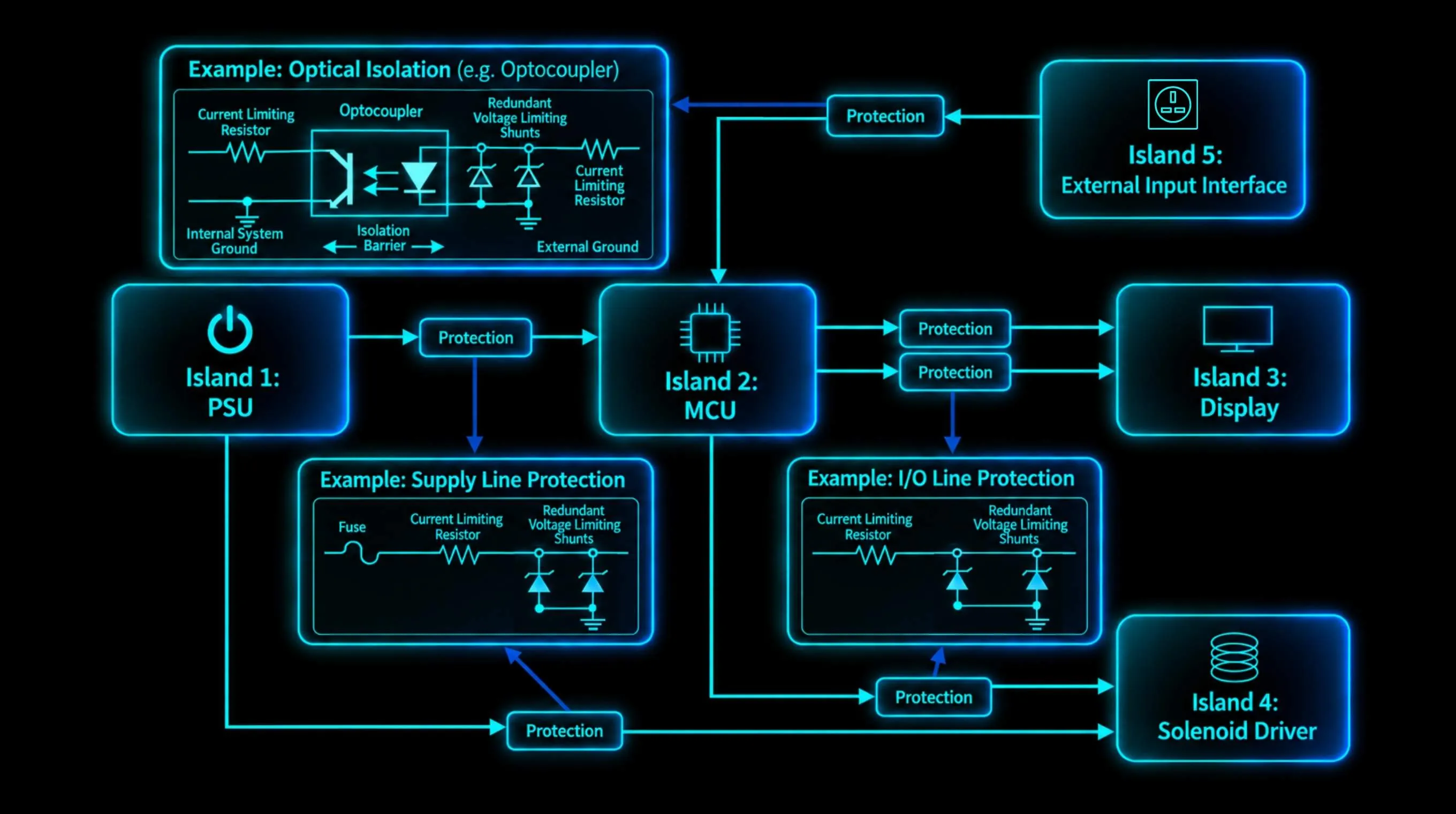
A key concept to manage failure modes is to define each part of the system as a discretely managed subsection, known as Islands. Interconnections between islands are implemented with clearly defined energy limits, breaking the system into manageable pieces. Each island is connected via energy limiting mechanisms, such as current limits (resistors, fuses), voltage limiting devices (shunts) that impose strict limits on transferred energy.
This strategy greatly facilitates fault assessment as the maximum energy present in any circuit may be readily determined by the defined entity parameters – the stated limits for input or output parameters through the interconnects. The task of assessment now becomes substantially simpler as no component will be subjected to greater stresses than those imposed by the entity parameters for the island in which it resides.
Thermal Management under Faults
Thermal faults assessed for each part of the system consider the worst-case fault energy present. One approach is to assume that all incoming power to an island is applied to one component, which constitutes the worst-case condition.
If all of the components in the island can be shown to remain within thermal limits under this worst-case scenario then this section of the system is demonstrably compliant.
This can result in some unreasonably large device requirements if approached incorrectly – it is important to know exactly which parameters are best applied when assessing each component.
An important distinction to note here is that the component does not need handle this worst-case load operationally as this is the power limit that may occur under fault conditions. The equipment has already failed in this situation. Specifically, the temperature rise in the part must not exceed the rated maximum temperature limit defined by the standard when this level of power is applied.
Limiting Available Energy – Minimising Spark Hazards
In addition to the requirements for thermal limits, the possibility of a spark causing ignition must be considered when flammable gases are present.
This has implications for stored energy devices such as capacitors and inductors. Tables document maximum values for energy storing components related to maximum operating voltage. These decrease rapidly with increasing voltage so operation at the lowest voltage practical will give greater design freedom.
Component Selection
Component selection is a critical part of Intrinsic Safety design, in particular, knowledge of failure modes. Components that do not have well-defined, predictable failure modes will often require direct testing. Some additional considerations in an effective part selection process that will greatly aid in producing a design that passes the approval process and facilitates ongoing manufacturing are discussed below.
Tolerances = freedom
Specifying parts with tighter tolerances where economically practical can buy the designer a small but useful measure of additional freedom. Fault calculations are based on worst-case limiting values applied all at once, supply voltage, minimum minimum resistor value, and so on. With tolerances taken at their most onerous limit, there can be a worthwhile amount of wiggle room keeping to the lowest tolerance value that is economically practical. For example, a power supply and a resistor both with 5% tolerance on parameters will cause an additional 12% worst-case dissipation compared to rating these items at 1%. In practice, the lowest ‘cheap’ tolerance is usually the better choice – i.e. 1% is highly favorable over 5%, but 0.1% tolerance with only a minor improvement in characteristics. At this level, availability of substitute components may also be an issue.
Don’t use ‘special’ parts
Another important point to bear in mind regarding ongoing production management is to avoid specialized parts wherever possible. Specifying ratings significantly different to the nominal for a generic component class may seem like a good solution during the initial design phase, however, parts with few equivalents can bring about unnecessary expense for future production – a BoM change requires re-submission of design documents as there will need to be additional approval processes conducted for the new components. In the case of schematic and / or PCB redesign these documents must also be re-submitted for approval. These processes incur additional cost and production delays that could be avoided by using generic or common parts whenever possible.
Don’t Over-Specify
An important point to consider when presenting a design for external review is that IS approval is applicable only for the parts as specified in the BoM presented.
A particularly useful approach giving considerable flexibility in manufacturing is to provide a BoM giving only the necessary specifications for generic parts. For example, if a part is defined in the IS BoM right down to the specific part number, then only that specific part may be used. However, if the part is specified as a generic set of specifications that define the requirements, then any part that meets the noted specifications may be used. This simple change to BoM organization potentially saves many future headaches and additional approval costs when dealing with out of stock or obsolete parts.
Conclusion
Ultimately, an effective design for Intrinsically Safe equipment will produce a set of documents that can be used to demonstrate compliance with the relevant standards that can be assessed by an independent testing body. Taking a structured approach to the design with failure modes assessed and managed throughout the design process ensures a smoother process with best prospects for approval without requiring significant rework. It is also advisable to keep one eye to the future, the savings from specific or specialist parts may well be outweighed by the cost of rework and re-certification if those parts become unavailable.