How We Validated Our PMSM Motor Against Real Data

From Analytical Models to FEM: Validating a PMSM Motor Model Against Real-World Data
I modeled a PMSM two ways and put it on a bench. The bench writes its own datasheet, and it didn't agree with the vendor about the magnets.
What the datasheet doesn't say
Permanent-magnet synchronous motors (PMSM's) drive EV's, drones, and robot joints. Their datasheets tend to run thin. A few rated-point numbers, a torque-speed curve, perhaps a back-EMF constant. What is rarely there, and rarely available on request, is the information a custom design needs: how small geometric details interact to determine torque and efficiency, how magnet shape and winding details combine in the airgap field, and where saturation begins to dominate.
That gap is what motor modeling is for. And once you're building your own model, the next question is whether to trust it. The answer requires putting a real motor on a bench. Old playbooks took weeks and still drifted from reality. The fix isn't a better single model, it's overlap: agreement across methods, plus contact with a bench. Neither happens for free; the constant checking is where an LLM coding agent, Claude Code, in my setup, multiplied my reach. Not by doing the physics, but by keeping it cheap to audit.
This work is one phase of a larger actuator effort: characterize an existing part by playing models against each other and against measurement, then steer the next iteration. The first thing the bench told me was that the magnets weren't what the spec said they were.
How I modeled it
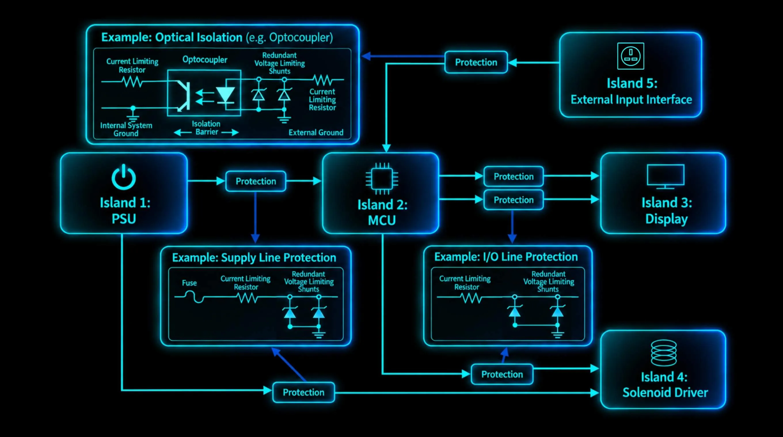
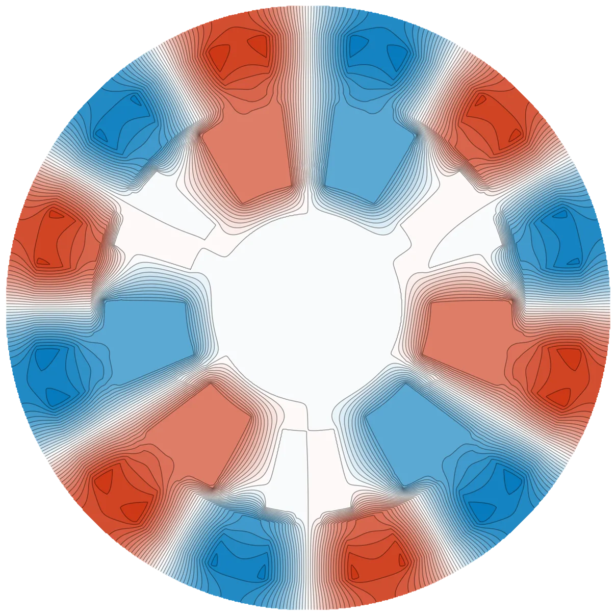
I ran this through phase-sweep, a general-purpose PMSM modeling pipeline. It's what tied the methods to each other and to the bench, and it's built around two independent solver families. Both predict the magnetic field across the air-gap, the millimeter of clearance between rotor and stator where torque actually gets made.
The analytical family is closed-form: equations you can solve on paper or compute in milliseconds, with a Carter factor that adjusts for how slot openings distort the field. The second is a 2D finite-element solver (NGSolve) that captures the actual magnetic-circuit geometry, in linear or nonlinear materials, paired with a one-parameter end-effect correction for the 3D flux paths a 2D solve can't see, itself a coefficient the validation has to test.
What the bench said first
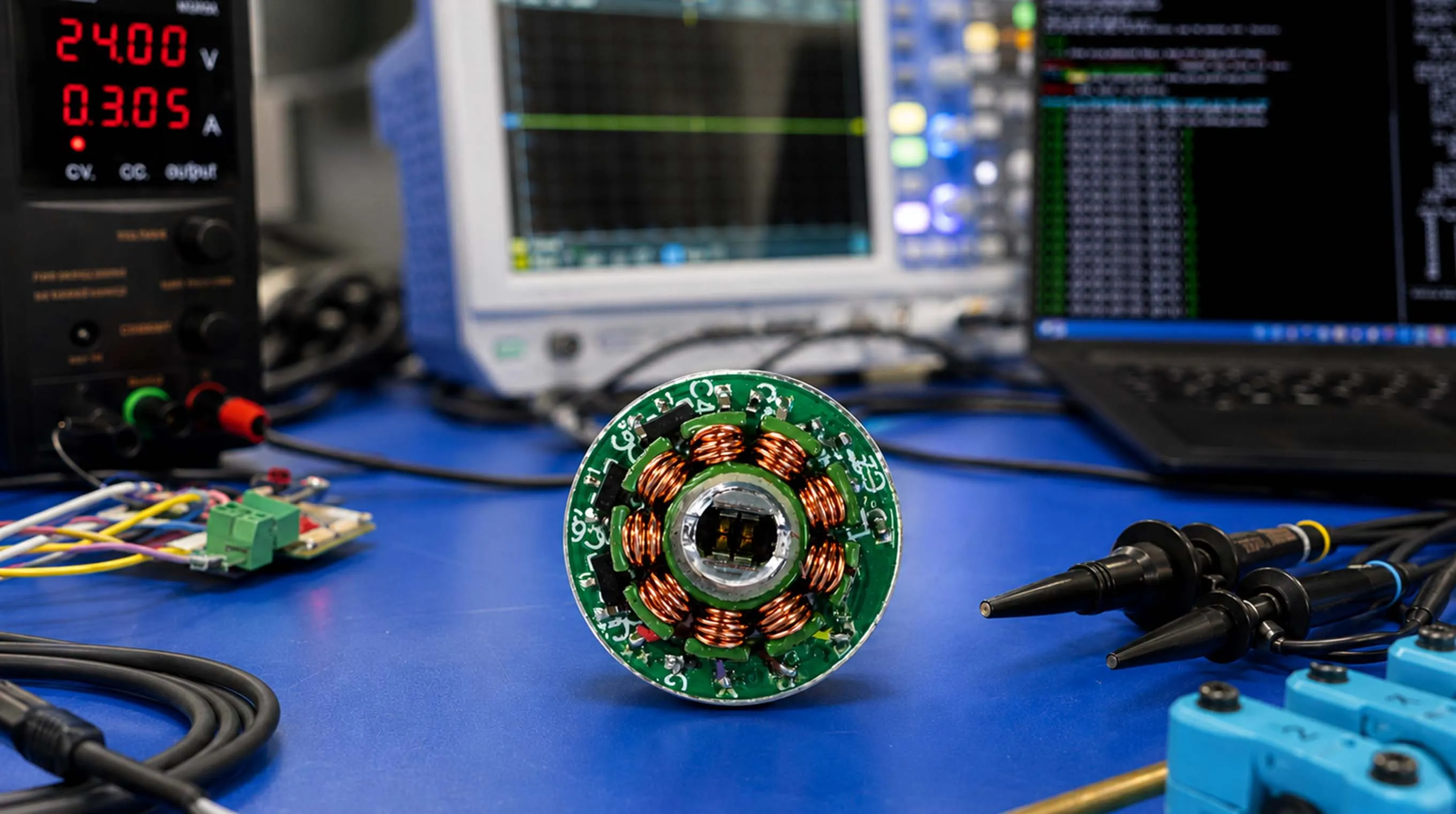
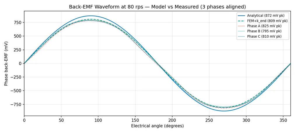
The motor under test was a twelve-pole, nine-slot outrunner actuator: the kind that drives a joint of a robotic arm. I captured open-circuit back-EMF (the voltage a motor generates when you spin it with no power applied) across the operating speed range. Magnet remanence, how strong the magnets are after magnetization, I treated as a fitted parameter.
Back-EMF is the cleanest cross-check: it isolates the rotor from controller tuning, current-loop artifacts, and thermal drift.
Here the bench gave me my first surprise. The vendor claimed an N52 grade, the strongest in common use. The back-EMF I measured at room temperature was consistent with N42 to N45, roughly 15–20% weaker. Magnets weaken with heat, but none of that gap came from temperature.
How wrong, and where
Three results, each one correction further along. A naïve smooth-stator analytical model overpredicted the measured back-EMF by 11.4%. A Carter factor brought that to 8.1%. Raw 2D finite-element analysis overpredicted by 17 to 19%; the end-effect correction closed the gap to within about 1%.
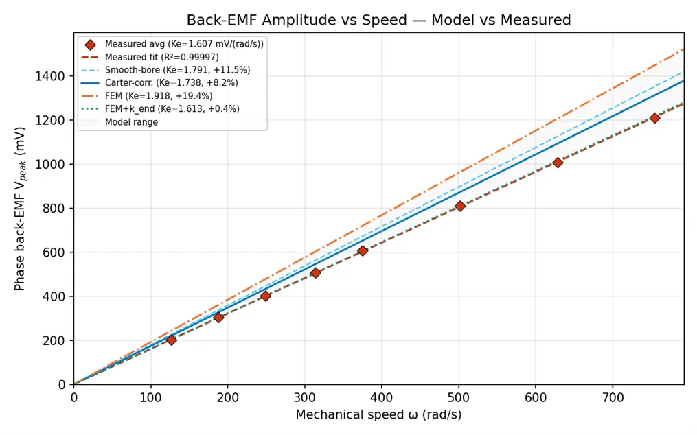
Getting the Carter factor right took an afternoon and a three-pass audit, numerical, plot-consistency, physics cross-reference. The third pass caught me. The formulation I used calls for the bore slot-opening width (the gap at the airgap surface), not the slot-body width; I had them swapped. The result was a 15% over-correction to the effective airgap, dragging the analytical prediction well below measured. Walking the coefficient back to Zhu & Howe (1993) surfaced the substitution, the citation was already in place.
Raw 2D FEM misses end-region leakage; for a motor this stubby, the magnetic stack is only a third of the diameter, the correction collapses it into a single coefficient, about 0.84 for this aspect ratio. The coefficient may also be absorbing bias from elsewhere in the model.
Fitting effective remanence converged on 1.34 tesla, within manufacturer tolerance and consistent with magnets sitting below their nominal grade. (The motor still worked, but under-grade magnets cost torque density.)
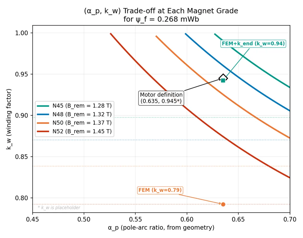
The takeaway lives in the contrast: high-fidelity tools without a calibration plan do not automatically outperform lower-fidelity tools with one, and the plan must be explicit enough to be proven wrong.
Why the agreement holds
Two things make this kind of validation trustworthy rather than just elaborate.
The first is that the models never stop checking each other. When a coefficient or a geometry shifts, both solver families re-solve, and any drift between them surfaces before it reaches a chart. Agreement between two independent methods isn't a result you screenshot once, it's a signal you can keep watching. Keeping it watchable, re-running every comparison, chasing each diff while it's still small, is the kind of constant, unglamorous work an agent multiplies, done after every change instead of only at milestones.
Take one of the published motors the pipeline is cross-checked against, Belkhadir 2023, an external-rotor design. When I audited my implementation against the source, three discrepancies surfaced. The biggest: the paper's 24-slot stator had been silently rendered as a smooth bore. The audit also turned up an arithmetic inconsistency in the paper's own table.
The second is that the bench anchors the one number the models can't supply on their own. Measured back-EMF feeds a one-knob fit, effective magnet strength, credible because the model carrying it has been audited line by line and the measurement pins the parameter being fit.
The physics still comes from references, derivation, and the bench, not from the agent. What changed was the cost of keeping the models honest, cheap enough that "do they still agree?" became a continuous check, not a milestone. Three models, hundreds of automated checks, four published reference motors, one bench.
The next motor
The validation is the warm-up; the next iteration is the point. The next build is being designed against trade-offs the vendor never documented, outer diameter, stack length, magnet grade, slot opening, with error bars the bench earned.
Next, the bench tests a motor designed from the calibrated simulation. I'll see how much of the guidance held, and the datasheet that matters is the one the bench writes.
References
Belkhadir, A., Pusca, R., Romary, R.,Belkhayat, D., Zidani, Y., & Rebhaoui, A. (2023). "Analytical and Finite Element Analysis for Demagnetization Fault of External Rotor PMSM. "IECON 2023, 49th Annual Conference of the IEEE Industrial Electronics Society,pp. 1–7. DOI: 10.1109/IECON51785.2023.10312419 (https://doi.org/10.1109/IECON51785.2023.10312419)
Zhu, Z. Q., & Howe, D. (1993)."Instantaneous Magnetic Field Distribution in Brushless Permanent Magnet DC Motors, Part III: Effect of Stator Slotting." IEEE Transactions on Magnetics, 29(1), pp. 143–151. DOI: 10.1109/20.195559 (https://doi.org/10.1109/20.195559)(Carter factor formulation.)
Zhu, Z. Q., Howe, D., & Chan, C. C.(2002). "Improved Analytical Model for Predicting the Magnetic Field Distribution in Brushless Permanent-Magnet Machines." IEEE Transactions on Magnetics, 38(1), pp. 229–238. DOI: 10.1109/20.990112 (https://doi.org/10.1109/20.990112)
Dependencies
NGSolve, open-source finite-element library (C++/Python). https://ngsolve.org
motulator, open-source motor-drive simulator (Aalto University). https://github.com/Aalto-Electric-Drives/motulator
phase-sweep, Lay, J. (2026) an analytical +FEM validation pipeline for PMSM air-gap fields.https://github.com/jonelay/phase-sweep